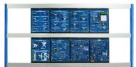
Microwave Active Circuit Design Trainer
Model:GOTT-MAC-157
Brand: GOTT
C/O: Malaysia
DESCRIPTION
- Design and implementation of microwave front end receiver module.
- Design and implementation of microwave front end transmitter module.
- Design and implementation of voltage controlled oscillator and phase locked loop.
- Design and implementation of IQ modulator and demodulator.
- Design and implementation of digital wireless transceiver module.
FEATURES
- Training for wireless communication technicians and engineers.
- To understand the applications and measurements of communication instrument XZs and products.
- Design and implementation ability training for microwave module circuit.
- To shorten the gap between academic and industrial circles.
- 2mm connect leads are used throughout the test point.
- 4mm connect leads are used throughout the DCV point.
- Each module can interlink together with U-link 4mm for 12v + 12v ground.
- 4mm LED indicator for each supply DCV + 12 v and -12v or + 5v and 5v.
PRODUCT MODULES DESIGN AND MEASUREMENT OF MICROSTRIP LINE MATCHING CIRCUIT
CODE 157-161
Design and Measurement of Microstrip Line Matching Circuit
- Experiment 1: Measurement ofλ / 4 Impedance Transformer Matchig Network (Operation Frequency: 2400 MHz; S11 < – 10 dB)
- Experiment 2: Measurement of Single and Balanced Short Stubs Matching Network (Operation Frequency: 2400 MHz; S11 < -10 dB)
- Experiment 3: Measurement of Single, Balanced and Radio Open Stubs Matching Network (Operation Frequency: 2400 MHz; S11 < -10 dB)
- Experiment 4: Measurement of and Open Stubs Matching Network (Operation Frequency: 2400 MHz; S11 < -10 dB)
DESIGN AND MEASUREMENT OF LOW NOISE AMPLIFIER & VOLTAGE CONTROLLED OSCILLATOR
CODE 157-162
Design and Measurement of Low Noise Amplifier (LNA)
- Experiment 1: Measurement of Frequency Responses (Operation Frequency: 2350 ~ 2450 MHz; S11 < -10 dB, S22 < -10 dB, S21 > -10 dB)
- Experiment 2: Measurement of Noise Figure (Operation Frequency: 2350 ~ 2450 MHz; NF < 1.8 dB)
- Experiment 3: Measurement of 1 dB Compression Point (Operation Frequency: 2400 MHz; S1dB > -15 dBm) Design and Measurement of Voltage Controlled Oscillator
- Experiment 1: Measurement of Oscillation Frequency and Output Power (Oscillation Frequency: 2350~2450 MHz; Output Power: > -5 dBm)
- Experiment 2: Measurement of Phase Noise (Phase Noise: -90 ~ -100 dBc/Hz @ 100 kHz)
- Experiment 3: Measurement of Gain Factor and Tunable Bandwidth (Gain Factor: 10 ~20 MHz/Volt; Tunable Bandwidth: 60 ~ 70 MHz)
- Experiment 4: Measurement of Pushing Figure (Pushing Figure: 8 MHz/Volt)
DESIGN AND MEASUREMENT OF PRE-AMPLIFIER POWER AMPLIFIER
CODE 157-163
Design and Measurement of Pre-amplifier
- Experiment 1: Measurement of Frequency Responses (Operation Frequency: 2350 ~ 2450 MHz; S11 < -10 dB, S22 < -10 dB, S21 > -10 dB)
- Experiment 2: Measurement of 1 dB Compression Point (Operation Frequency: 2400 MHz; S1dB > 5 dBm)
- Experiment 3: Measurement of 3rd Order Intercept Point (Operation Frequency: 2400 MHz; OIP3 > 25 dBm Design and Measurement of Power Amplifier
- Experiment 1: Measurement of Gain Flatness (Operation Frequency: 2350 ~ 2450 MHz; Gain Flatness: ±1.5 dB)
- Experiment 2: Measurement of 1 dB Compression Point (Operation Frequency: 2400 MHz; S1dB > 23 dBm)
- Experiment 3: Measurement of 3rd Order Output Intercept Point (Operation Frequency: 2400 MHz; OIP3 > 40 dBm)
- Experiment 4: Measurement of the Ratio of Fundamental and Harmonics (Operation Frequency: 2400 MHz)
DESIGN AND MEASUREMENT OF PHASE LOCKED LOOP CONTROLLER & PHASE LOCKED LOOP
CODE 157-164
Design and Measurement of Phase Locked Loop Controller
- Experiment 1: LCD and Keypad Testing (Locked Frequency Display: Locked Status Detection)
- Experiment 2: MB 15E07 Control Signal Testing (Locked Frequency: 2250 ~2350 MHz; Stepped Frequency: 1 MHz, 10 MHz) Design and Measurement of Phase Locked Loop
- Experiment 1: Measurement of Frequency Responses for Loop Filter (3-dB Frequency: 12.5 kHz)
- Experiment 2: Measurement of PLL and Phase Noise (Phase Noise < -100 dBc/Hz @ 100 kHz)
- Experiment 3: Measurement of PLL Locked Time (Locked Time < 5 ms)
DESIGN AND MEASUREMENT OF BALANCED MIXER & IMAGE-REJECTION MIXER
CODE 157-165
Design and Measurement of Balanced Mixer
- Experiment 1: Measurement of Conversion Loss vs. LO Power (RF: 2420 MHz, LO: 2350 MHz; Conversion Loss: < 15 dB) Experiment 2: Measurement of Conversion Loss vs. RF Power (RF: 2420 MHz, LO: 2350 MHz; Conversion Loss: < 15 dB, S1dB > 0 dBm)
- Experiment 3: Measurement of 3rd Order Intercept Point (RF: 2420 MHz, LO: 2350 MHz; OIP3 > 10 dBm)
- Experiment 4: Measurement of IF bandwidth (RF: 2360 ~ 2450 MHz, LO: 2350 MHz; IF bandwidth: > 100 MHz)
- Experiment 5: Measurement of Isolation (Operation Frequency: 2350 ~ 2450 MHz; Isolation: > 20 dB) Design and Measurement of Image-rejection Mixer
- Experiment 1: Measurement of Conversion Loss vs. LO Power (RF: 2420 MHz; LO: 2350 MHz; Conversion Loss: < 15 dB)
- Experiment 2: Measurement of Conversion Loss vs. RF Power (RF: 2420 MHz; LO: 2350 MHz; Conversion Loss: < 15 dB, S1dB > 5 dBm)
- Experiment 3: Measurement of 3rd Order Intercept Point (RF: 2420 MHz; LO: 2350 MHz; OIP3 > 15 dBm)
- Experiment 4: Measurement of Isolation (Operation Frequency: 2350 ~ 2450 MHz; Isolation: > 30 dB)
- Experiment 5: Measurement of Image-rejection level (RF: 2250 ~ 2350 MHz; LO: 2350 MHz; Image-rejection level: > 30 dB)
DESIGN AND MEASUREMENT OF IQ MODULATOR & IQ DEMODULATOR
CODE 157-166
Design and Measurement of IQ Modulator
- Experiment 1: Measurement of PSK Modulator (Operation Frequency: 70.7 MHz; Data Rate: >100 kbps)
- Experiment 2: Measurement of QPSK Modulator (Operation Frequency: 70.7 MHz; Data Rate: >100 kbps) Design and Measurement of IQ Demodulator
- Experiment 1: Measurement of PSK Demodulator (Operation Frequency: 70.7 MHz; Data Rate: >100 kbps)
- Experiment 2: Measurement of QPSK Demodulator (Operation Frequency: 70.7 MHz; Data Rate: >100 kbps)
DESIGN AND IMPLEMENTATION OF DIGITAL WIRELESS TRANSMITTER
CODE 157-167
Design and Implementation of Digital Wireless Transmitter
- Experiment 1: Measurement of Output Power(Operation Frequency: 2400 MHz; Pout > 10 dBm)
- Experiment 2: Measurement of Harmonics’ Output Power(Operation Frequency: 2400 MHz; Pout < -45 dBm)
- Experiment 3: Measurement of Modulation Signal (Operation Frequency: 2400 MHz; Type of Modulation: FSK)
DESIGN AND IMPLEMENTATION OF DIGITAL WIRELESS RECEIVER
CODE 157-168
Design and Implementation of Digital Wireless Receiver
- Experiment 1: Measurement of Sensitivity (Operation Frequency: 2400 MHz; Receiver Sensitivity: > -80 dBm)
- Experiment 2: Measurement of Demodulation Signal (Operation Frequency: 2400 MHz; Type of Demodulator: FSK)
- Experiment 3: Measurement of Image-rejection Ability (Operation Frequency: 2400 MHz; Image-rejection level: > 30 dB)
Manuals:
- All manuals are written in English
- Model Answer
- Teaching Manuals
General Terms:
- Accessories will be provided where applicable.
- Manuals & Training will be provided where applicable.
- Designs & Specifications are subject to change without notice.
- We reserve the right to discontinue the manufacturing of any product.