StepperMotorWithPLCTrainingSystem
Model: GOTT-PLC-STP
Brand:GOTT
C/O:Malaysia
DESCRIPTION
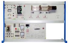
The GOTT Stepper Motor System is an integrated system for in depth studies Stepper Motor theory and working principles. The system comes with an upright control panel. The stepper motor system is connected via flexible coupling. The control panel comprises of Stepper Motor Driver, Time Delay Contactor, Programmable Logic Controller Unit, PLC Input Terminal Unit, I/O Unit, PLC Output Terminal Unit, and all wiring connections brought out to 4mm terminals. Connecting leads with banana plugs facilitate quick and easy connections between the Stepper Motor System and other control. The Step Motor Unit stands independently with its own power input to simulate the frequency of the stepper motor. The operational and experimental manuals are provided in English.
FEATURES
- Works with Existing Equipment
- Equipped with manual switches to simulate all inputs and outputs
- Accommodates other PLC Brands too
- Actual Stepper motor control
- Integration between stepper motor driver and programmable logic controller unit
- Actual stepper motor unit with sensors for further study of motion control
- Easy connecting ability to existing motor sensors, valves and switches through standard banana jacks
- Can be combined with other control devices included industrial sensors and other mechatronics training equipment.
PRODUCT MODULES
MAIN SUPPLY UNIT
CODE 478-001
Leakage Current: 30mA CAM Switch : 3-Pole Emergency Stop
DC POWER SUPPLY
CODE 478-002
Protection Fuse: 3A Dual output: 0…30VDC ±15VDC Input: AC 240V, 50Hz 1-Phase
STEPPER MOTOR DRIVER
CODE 478-003
Mode of Operation: Step & Direction, CW & CCW 15 Switch Selectable Step Resolution Up to 200kHz Step Clock Rate LED Indicating Power & Fault Status
I/O UNIT
CODE 478-004
Stepper Motor Driver I/O Unit
PUSH BUTTON
CODE 478-005
Rated Voltage: 240VAC Contact: NO & NC Push Button: On & Off button
TIME DELAY CONTACTOR
CODE 478-006
Coil Voltage: 240VAC Contact: NO & NC
STEPPER MOTOR UNIT
CODE 478-007
Sensor Limit: Home, Left & Right Indicator for Sensor Condition Input: 5…24VDC
STEP MOTOR MODULE
CODE 478-008
Frequency Ranges: 5Hz,50Hz, 100Hz, 500Hz, 1kHz & 5kHz Counter Reset function Direction: CW or CCW
PLC INPUT TERMINAL UNIT
CODE 478-009
Indicator 24VDC x 16 units Output: 24VDC Input: Connect to PLC
PLC OUTPUT TERMINAL UNIT
CODE 478-010
Indicator 24VDC x 8 units 4mm Socket x 8 units Output: 24VDC Input: Connect from PLC
PROGRAMMABLE LOGIC CONTROLLER UNIT
CODE 478-011
- 16 input & 8 output.
- Frequency pulse output function.
- Cam switch function.
- Frequency counter function.
- 4 high speed interrupt inputs.
- 2 channel high speed counters.
SAFETY CONNECTING LEAD
CODE 237-001
4mm connecting lead
VERTICAL FRAME
CODE 380-000
High level : DIN standard A4 with two shelves Material: Aluminium Side Frame: T shape Size: 2-Layer 1450mm Length
EXPERIMENT MANUAL
CODE 478-012
EXPERIMENT TOPICS :
- Fundamentals of Logic
- Programming Language
- Developing Ladder Logic Programs
- Programming timers
- Structure of Control Systems
- Sequencer Programs
- Programming Counters
- Master Control and Zone Control Instructions
- Jump Instructions and Sub-routines
- Combined Counter and Timer Functions
Manuals:
- All manuals are written in English
- Model Answer
- Teaching Manuals
General Terms:
- Accessories will be provided where applicable
- Manuals & Training will be provided where applicable.
- Designs & Specifications are subject to change without notice.