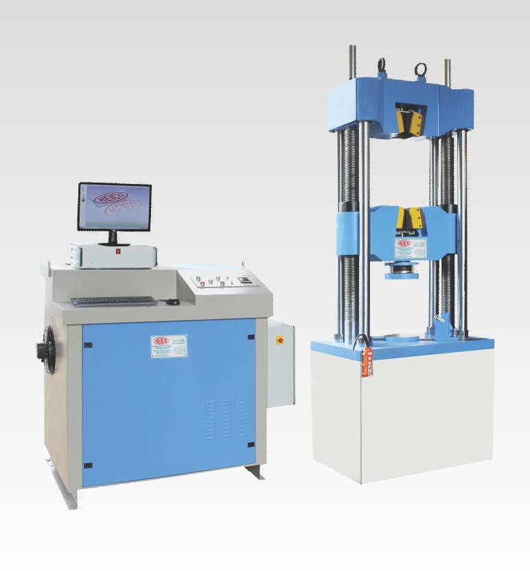
| computerized Universal Testing Machine with open front loading jaws (hydraulic) supplied Software 1000kN capacity.
Model: HL590.25 (FL) Brand: HEICO C/O: India
Technical Specification: computerized Universal Testing Machine is suitable to conduct following tests – (i) Compression (ii) Tension (iii) Transverse (iv) Bending (v) Shear (vi) Hardness and many others on various types of ferrous and non-ferrous materials conforming to testing procedure laid down in IS/ ASTM etc. standards.
computerized Universal Testing Machine is fast, accurate & simple to operate. In these machines load and displacement are displayed on the digital display unit or monitor in the respective engineering units. Digital display unit has RS 232/ USB connectivity to computer for real time transfer data to computer. When connected to computer online graph can be displayed on the screen. These machines are supported by windows based user friendly software which can store, retrieve readings as and when required.
The machine comprise of three main parts. (A) Loading Frame (B) Hydraulic Pumping System (C) Electronic Control Panel
(A) Loading Frame The Loading Frame consists of a central cross head whose position is adjustable through a geared motor depending on the size of the test specimen. The lower table is carried by the piston of the Hydraulic Ram of suitable capacity positioned in the cast iron base of the machine. The upper cross head is carried by four steel columns fixed to the lower table. The machine have six pillars in total for stability and rigidly. Compression, transverse, bending, shear and hardness tests are carried out between the central cross head and lower table while the tension test is carried between the central and upper cross heads. Sensing of load is through a strain gauge based transducers, while the movement of the lower table (ram Stroke) is measured by rotary encoder. Safety features like over travel limit for central cross head, over travel limit for ram and over loading of the system are provided as standard with the machines.
(B) Hydraulic Pumping System
Hydraulic pumping system consists of multi plunger pump powered by a suitable motor operated on 415V, 3Phase, 50Hz. This pump gives a continuous non pulsating oil flow to the ram of the loading frame. Pressure switch is provided for additional safety against over load. Release valve and load control valve is placed at a convenient position for easy operation by the operator. It also have electrical control panel for the movement of the middle cross head and also for ON/OFF of the main pump. Additional switch is provided for fast lift of the ram for initial filling of the gap. The system is supplied with manual pacing arrangement with status of pace rate
Load Pacing:
The system is supplied with manual pacing arrangement with status of pace rate is indicated in the digital display unit. Pace rate is achieved manually by controlling the flow control knob and the system is released manually after the peak load is achieved.
(C) Electronic Control Panel It is a microprocessor based unit with a built-in interface for the computer. The panel consists of a load indicator, elongation indicator and an output analog port for X-Y/t plotter. It has the facility for Tare, Peak Hold, Auto zero, Auto ranging, i.e. automatic shifting of range from lower to higher after the load reaches the set limit and reset button, Start and stop of transferring data to computer. The readings of Load and Elongation can be transferred to computer through RS 232 port and can be online monitored.
Microprocessor Based Touch Panel Display & Data Acquisition System for UTM
The two channel micro processor based signal conditioning and touch panel display unit is suitable to measure load, displacement and extensometer (Optional) directly indicated in their respective engineering units. Load is indicated in terms kN and extension/ displacement in mm. the load is being measured by the pressure transducer and displacement is measured by rotary encoder/linear displacement transducer. The system receives the output signals of the both the channels as its inputs and amplify the same to be displayed on the touch panel display at the front panel. The data of both the channels of UTM can be transferred to computer through RS-232/ Ethernet and can be online monitored in the software
Salient Features of System Menu driven interface Facility to perform various operations such as TARE, PROGRAMMING, START, STOP etc. from touch panel display Programmable rate of loading (Pace Rate) and sample parameters (Shape, Dimension etc.) through touch panel display Standalone system to start and stop of test Manual pace rate control as preset value with pace deviation Bar Online display of load, peak load and displacement with recording of peak load along other sample details Real tine plotting of load vs displacement load vs extensometer curve Storing of results in user defined file with sample parameter and other details Real time clock to keep automatic track of the date, time and runs Transmission of data to computer through Ethernet/USB/RS232 port
Laptop: Intel Core i3, 5010U, 5th generation processor, 4 GB Ram, 500 GB HDD, dvd rw, 14” screen, HD cam.
Application Software: Easy to use Software would be given the framework to get and plot information on the web and afterward dissect the different outcome boundaries.
Salient Features of the Software: Windows based & user friendly On line display of Load & Displacement Saving & Retrieving of Test Files Start & Stop operation for acquiring data Online Plot of Load v/s Displacement Graph Display of recorded Data on the Screen Storing of Data in Numeric form Calculation of various parameters (Tensile Strength, Young’s Modulus, Yield Stress, Ultimate Stress, Max. Strain etc.) Facility to print the data and all the graphs.
Technical Data: Maximum Capacity (kN)- 1000 1st. Measuring Range (kN): 0-200 Least Count (N)-100 2nd. Measuring Range (kN): 200-1000 Least Count (N)-1000 Clearance for tension test (mm): 50-850 Clearance for compression test (mm): 0-85 Ram Stroke (mm)-250 Piston speed at no load(mm/min): 0-80 Clearance between columns (mm)-750 connected load (KW)-3.5 Operating Voltage: 400-440 Phase-3
Standard Accessories Supplied with Machine: For Tension Test Clamping Jaws for: 10-25 Round specimens (mm): 25-40 Clamping Jaws for flat: 0-20 specimen (mm): 20-40 Width of specimen (Max.) (mm): 75
For Compression Test Diameter of platens (mm): 250
For Transverse Test Diameter of rollers (mm): 50 Length of rollers (mm): 170 Max. span between the rollers: 800
also visit our facebook page |