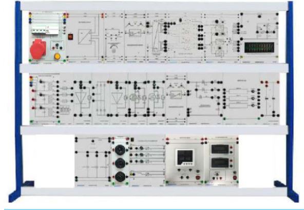
Power Electronics Training Kit
Brand: GOTT
Model: GOTT-PET-588A
C/O: Malaysia
DESCRIPTION
The Power Electronics Training Kit has been designed to control of electrical energy with the greatest efficiency possible. In fact, it allows the implementation of theoretical-practical courses, for the study of power electronics. The individual units of an experimental set-up are connected via 4mm safety sockets which are arranged in large, synoptically graphical symbols and current flow diagrams. Due to the vertical arrangement of the experimental panels, the experimental set-up can be seen from a far distance and can be adapted step by step to the course of the lessons or lectures. The experiments permit practice-oriented, hands-on training to be carried out, thus assuring the trainees of the proficiency needed to handle the tasks and the equipment found in this field. The training panels and functional units with block circuit diagrams and signal diagrams permit clear and understandable assembly of the experiment circuits.
PRODUCT MODULES
AC POWER SUPPLY
CODE:588-001
FCCB x 1 unit
Mains Contraol Lamps x 3 units 4mm safety sockets
Output : 415V DC : 230V/1A
Input : AC 415 , 50Hz 3 Phase
THREE PHASE TRANSFORMER
CODE:588-021
Protection Fuse 3A x 3
Input : 415v 3phase
Output: AC: 3 x 90V/1.5A with 3 center taps 45V 4mm safety sockets
FOUR CHANNELS ISOLATION AMPLIFIER
CODE 588-021
Channels can be switched on or off individually
Frequency Range: DC … 80kHz
Voltage: Max 620VDC/440VAC Overdrive indication with LEDs 4mm Safety Sockets
Input: AC 240V, 50Hz 1-Phase
CONTROL UNIT SIX PULSE
CODE 588-006
Single pulse or pulse train operation Phase shift can be set for various natural commutating points: 0°, 30°, 60°
Output:
- Synchronize Voltage: 1…440VAC
- Control Voltage: 0 … +10VDC Input: ±15VDC
CONTROL UNIT TWO PULSE
CODE 588-005
Single pulse or pulse train operation Phase shift can be set for various natural commutating points: 0°, 30°
Output:
- Synchronize Voltage: 1…250VAC
- Control Voltage: 0 … +10VDC Input: ±15VDC
THYRISTOR WITH TURN OFF CIRCUIT
CODE 588-016
Main Thyristor and Turn-off Thyristor:
- VDRM: Max 800V
- IT AV: Max 13A
- TQ: 35μs
Free-wheeling Diode:
- VRRM: Max 1000V
- IT AV: Max 8A
- Shunts: 4 x 0.1 ohm, 1% Turn-off Capacitor: 4μF, 450V Ring-around reactor: 1mH
CONTROL UNIT PWM / PFM
CODE 588-007
Operation can be selected with the following control modes: Pulse Width Modulation (PWM) and Pulse Frequency Modulation (PFM)
Control voltage: 0 … +10VDC
Pulse Width Modulator
- Frequency Ranges: 20 … 200Hz / 0.2 … 2kHz / 2 … 20kHz
- Pulse Duty Factor tON: 0 … 0.95 Pulse Frequency Modulator
- Pulse Duration Ranges: 5 … 50μs / 50 … 500μs / 0.5 … 5ms
- Frequency: 20Hz … 20kHz
Output Amplifier
- Sustained short-circuit proof
- Indication of switching state via 2 LEDs
- INHIBIT input Input: ±15VDC
REFERENCE VARIABLE GENERATOR
CODE 588-003
Output: (selectable using bridging plug)
- 0 … +10VDC
- -10VDC … +10VDC
Input: ±15VDC
TRIGGER POINT LIMITER
CODE 588-004
LED indication for overlap
Rectifier Stability Limit: 0° … 180°
Inverter Stability Limit: 180° … 0°
Input: ±15VDC
IGBT
CODE 588-014
VCES : Max 1000V
IC AV : Max 10A
VCE SAT : 3.5V
CGE : 1.8Nf
SINGLE PHASE RECTIFIER
CODE 588-029
Periodic Repetitive Peak Reverse
Voltage: 500V
On-State Current: 10A
Protection: Fast Acting Fuse With R-C-D suppressor circuit
FUSE
CODE 588-009
Rated voltage : 415VAC Protection Fuse 2A x 3 units
POWER DIODE
CODE-588-010
VRRM: Max 1000V IF RMS : Max 10A
TRIAC
CODE 588-015
VRRM: 800V
CAPACITOR UNIT
CODE 588-018
Nominal Capacitance: 2 x 1000μF Nominal Voltage : 415V
RECTIFIER
CODE 588-011
Nominal Voltage: 3 x 400V
Nominal Current: 10A
Surge Forward Current: 300A
MOSFET
CODE 588-013
VDS: Max 500V
ID: Max 10A
RDA(ON) : 0.6Ω 4 Each
BULB SOCKET
CODE 588-020
Incandescent Lamp x 3 units Input: AC 240V, 50Hz 1-Phase
RESISTOR LOAD
CODE 588-017
Resistor 100Ω x 3 units Protection Fuse 1A x 3 units
DC POWER SUPPLY
CODE 588-002
Two red LED (Voltage monitor) 4 mm Sockets
Output: ±15VDC & +5VDC
Input: AC 240V, 50Hz 1-Phase
THYRISTOR
CODE 588-012
Thyristor x 6 units Protection Fuse 1.5A x 6 units
VRRM: Max 1000V
IF RMS : Max 12A
ELECTRICAL METER
CODE 588-038
Voltmeter range: 0…500VAC
Ammeter range: 0…5A
Input: AC 230V, 50Hz 1-Phase 2 Each
DC MEASUREMENT UNIT
CODE 159-008
Voltmeter range: 0…500VDC
Ammeter range: 0…5A
Output: 230VDC
Input: AC 230V, 50Hz 1-Phase 2 Each
RLC LOAD
CODE 588-019
Resistor 1kΩ
Inductor 50mH 2.5A with tap at 12.5mH
Capacitors 4/8/16μF, 450VAC
SAFETY U -LINK
CODE 446-000
A unit which is wed to link the unit together
SAFETY CONNECTING LEAD
CODE 237-001
4mm connecting leads
FAULT SIMULATOR PHASE CONTROL
CODE 588-008
A total of 20 faults from the following categories can be switched on:
- Interruption
- Faulty assembly
- Short-circuit Faulty components
- Input: AC 240V, 50Hz 1-Phase
U-LINK
CODE 159-019
A unit which is wed to link the unit together
VERTICAL FRAME
CODE 297-000
High Level: Din Standard A4 with two shelves
Material: Aluminium Side Frame: T shape
Size: 3-Layer 1450mm Length
EXPERIMENT MANUAL
CODE 588-032
EXPERIMENT TOPICS :
The Power Electronics Training Kit makes it possible to build up straightforward experimental circuits in keeping with practical requirements. Groups of experiments on basic power electronic circuits are presented, demonstrated and explained on the basis of rectifiers in a tried-and-tested didactic manner and sequence.
- Single-Phase Half-Wave Half Controlled Rectifier Circuit
- Single-Phase Full-Wave Controlled Rectifier Circuit
- Single-Phase Bridge-Type Controlled Rectifier Circuit
- Single-Phase AC Booster Circuit
- Three-Phase Bridge-Type Controlled Rectifier Circuit
- Quenching Circuit Step-Down DC Chopper Module
- MOSFET Step-Down DC Chopper Circuit
- IGBT Step-Down DC Chopper Circuit
- Passive Inverter Circuit
- Fault Simulator
- Connection Diagram
Manuals :
- All manuals are written in English.
- Teaching Manuals
General Terms :
(1) Accessories will be provided where applicable.
(2) Manuals & Training will be provided where applicable.
(3) Designs & Specifications are subject to change without notice.
(4) We reserve the right to discontinue the manufacturing of any product